What Is an Agitator and How Does It Work?
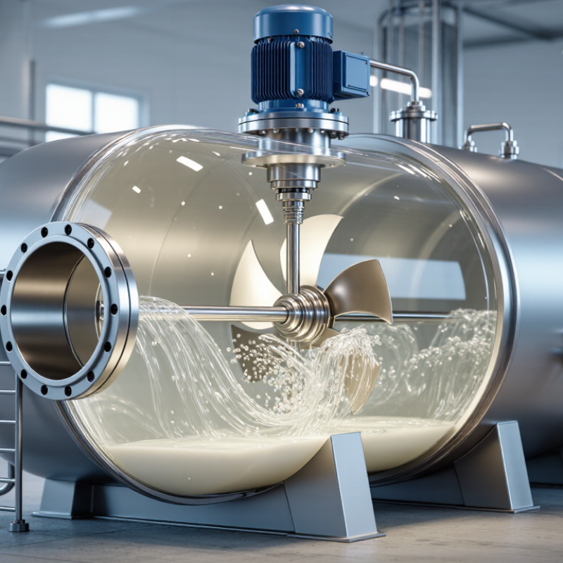
An agitator is a mechanical device that moves liquid, powder, or suspended solids inside a vessel. It usually combines a motor, shaft, impeller, and support structure. Together, these components create controlled movement within the process material. Agitators are common in chemical plants, food factories, wastewater facilities, pharmaceutical production, and many other industries.
Inside a tank, the motor turns the shaft at a selected speed. The impeller then pushes the material in a radial, axial, or mixed-flow pattern. This movement can blend ingredients, keep particles suspended, improve heat transfer, or support chemical reactions. For example, a pitched-blade impeller may lift liquid from the tank bottom, while a turbine design can create stronger circulation near the vessel walls. A properly chosen agitator helps prevent dead zones, where material barely moves.
Agitators are not simply high-speed mixers. Their performance depends on viscosity, density, tank geometry, fill level, temperature, and impeller clearance. A design that works well for water may struggle with syrup or wet powder. Real systems are messier. Even experienced engineers may need testing, measurement, and adjustment before achieving stable results. Power consumption also matters, because excessive speed can create foam, heat, or unnecessary equipment stress. Understanding how Agitators work helps operators select safer settings, recognize uneven mixing, and maintain reliable production quality. This article examines their main parts, operating principles, common designs, and practical limitations.
Agitator Definition and Its Role in Industrial Mixing Systems
What Is an Agitator and How Does It Work?
Agitator Definition and Its Role in Industrial Mixing Systems
An agitator is a mechanical device that moves fluid inside a tank. Its shaft, blades, and motor create controlled circulation. This movement distributes solids, liquids, heat, or dissolved gases throughout the vessel.
In industrial mixing systems, the agitator does more than “stir.” It manages blending time, suspension quality, temperature uniformity, and process consistency. A low-speed impeller may gently combine sensitive liquids. A high-shear design can break droplets or disperse powders. The correct choice depends on viscosity, density differences, tank geometry, and required shear. Small design errors matter. A poorly positioned blade can leave stagnant zones near the tank wall.
The International Energy Agency reported that industry consumed about 37% of global final energy in 2022. This makes efficient mixing increasingly important. The U.S. Department of Energy also identifies motor-driven systems as major industrial energy users. Agitator efficiency depends on more than motor rating. Impeller diameter, speed, gearbox losses, and operating time all influence energy demand. A practical review should measure torque and batch results, not rely only on catalog calculations.
Tips: Start with pilot trials. Record viscosity changes during processing. Check the bottom, corners, and liquid surface for uneven movement. Reduce speed when acceptable, but confirm that solids remain suspended. A perfect blend is not always necessary. The cheapest setting may still create rework, and that possibility deserves honest testing.

Agitator Components: Motors, Shafts, Seals, Baffles, and Impellers
An agitator creates controlled movement inside a tank, helping liquids, slurries, or suspended solids behave consistently. Its motor provides rotational energy, while a gearbox may adjust speed and torque for the process. The shaft carries that rotation into the vessel and must resist bending, vibration, and corrosion. In field inspections, shaft alignment often reveals problems before operators notice unusual noise. Small errors matter.
An impeller turns mechanical power into fluid flow. Radial impellers push material outward, while axial designs move it vertically through the tank. Baffles interrupt circular swirling and improve top-to-bottom mixing. Without suitable baffles, the liquid may rotate as one mass instead of mixing effectively. Seals protect the vessel boundary where the rotating shaft enters. Seal selection depends on pressure, temperature, abrasive particles, and chemical compatibility. A leaking seal is not always a seal failure; poor installation or shaft runout can also be responsible.
Reliable agitator design begins with the actual process, not a standard component list. Engineers should check viscosity changes, fill level, density, heat transfer needs, and cleaning conditions. Motor sizing must allow startup load, especially when settled solids have formed overnight. Shaft diameter and impeller clearance deserve equal attention. That part is easy to underestimate. During maintenance, inspect bearings, coupling alignment, seal faces, and baffle welds. Records help, although real equipment rarely behaves exactly like a calculation. I would treat test results as evidence, not absolute truth, and adjust the design when operating data disagrees.
How Impeller Rotation Creates Axial and Radial Fluid Flow
An agitator is a mechanical device that moves liquid inside a tank. Its motor turns a shaft, and the shaft rotates an impeller. This rotation transfers energy into the fluid. The result is controlled circulation, mixing, and heat distribution.
Impeller rotation usually creates axial flow, radial flow, or both. Axial flow moves liquid parallel to the shaft. It pushes fluid downward or upward, forming a circulation loop through the tank. This action helps suspend solid particles and reduce temperature differences. Radial flow moves liquid outward from the impeller toward the tank wall. It produces strong shear and improves dispersion between liquid phases. Think of a rotating fan beneath the surface.
Impeller shape, speed, liquid depth, and tank geometry change the flow pattern. A small speed increase can greatly raise turbulence and power demand. Real tanks rarely behave perfectly. Baffles may limit swirling, but poorly positioned baffles can create dead zones. Field measurements often reveal circulation paths that computer models miss. That detail matters.
Fluid viscosity also changes performance. Thin liquids respond quickly, while thick fluids may move slowly near the tank walls. A radial impeller can disperse droplets effectively, yet it may not suspend heavy solids well. An axial impeller may lift solids efficiently, but excessive speed can damage delicate materials. Engineers must match impeller action to the process, not simply choose the fastest rotation. Even a well-designed system deserves testing.
Agitator Sizing: Reynolds Number, Power Number, and 0.3–0.5 D/T Ratios
An agitator keeps a vessel’s contents moving, blending liquids, suspending solids, or improving heat transfer. Its performance depends on more than motor speed. Impeller diameter, fluid properties, tank geometry, and baffles all influence the final result.
Reynolds number helps identify the mixing regime. It is calculated as Re = ρND²/μ, where ρ is density, N is rotational speed, D is impeller diameter, and μ is viscosity.
Low values indicate laminar flow, while high values suggest turbulent flow. The transition zone can be less predictable. Careful testing matters there.
The power number connects impeller design with energy demand:
Rearranging gives P = NpρN³D⁵.
Engineers often begin with an impeller-to-tank ratio between 0.3 and 0.5 D/T. A 0.4 ratio may provide balanced circulation in a moderate-viscosity liquid. It is not a universal answer. A small impeller running quickly can consume similar power while creating different shear and flow patterns. Tank baffles, liquid height, and solids loading can change the result significantly.
A practical sizing check should compare calculated power with torque, motor capacity, startup load, and actual operating viscosity. A spreadsheet may look exact while its assumptions remain weak. Trial observations, such as surface drawdown, dead zones near the wall, or settled particles after shutdown, can reveal problems equations miss. Safety margins should be documented, not quietly guessed.
Operating Data: 1–10 m/s Tip Speeds and Low-to-High Shear Applications
What Is an Agitator and How Does It Work?
Operating Data: 1–10 m/s Tip Speeds and Low-to-High Shear Applications
An agitator moves liquid, solids, or gas through a vessel by rotating an impeller. Its tip speed describes how quickly the impeller edge travels. Operators calculate it from impeller diameter and rotational speed. This value helps connect equipment settings with mixing behavior.
Tip speeds near 1–3 m/s usually suit gentle blending, suspension support, and heat transfer. They create steady circulation without excessive turbulence. A tank may show a slow surface roll, while the lower liquid zone remains evenly mixed.
Speeds around 3–6 m/s provide stronger dispersion and faster blending. They can also increase power demand and fluid temperature.
Higher tip speeds, commonly 6–10 m/s, support high-shear duties such as particle breakup and liquid dispersion. These applications need careful control. Excessive shear may damage sensitive materials or draw unwanted air into the batch. A simple speed chart is useful, but it can mislead. Viscosity, impeller shape, tank geometry, and fill level also change performance. Experienced operators often check torque, motor load, temperature, and sample consistency together. A trial run may reveal uneven circulation that calculations miss. In practice, the best setting is not always the fastest one.