What Are the Best Optical Inspection Tools in 2026?
Choosing the best Optical Inspection Tools in 2026 depends less on a single specification and more on the work they must perform. A production line checking tiny surface defects needs different equipment from a lab measuring a component’s shape. Options include digital microscopes, machine-vision cameras, borescopes, 3D optical profilers, and interferometers. Each reveals different details. Some show a wide area quickly; others capture fine features or measure height without contact.
This guide compares tools by resolution, repeatability, field of view, inspection speed, lighting control, software, and integration needs. It also considers setup and ongoing calibration, since a sharp image alone does not guarantee a reliable measurement. On a factory floor, glare, vibration, and changing part positions can affect results. In a lab, sample preparation and measurement conditions still matter. Small details count.
A practical comparison should use representative samples and consistent settings, then verify results against known measurements where possible. Vendor specifications are useful, but they do not replace a trial under real working conditions. A neat spec sheet can still mislead. And no tool fits every task. The sections ahead explain which inspection methods suit common applications, what trade-offs to expect, and which questions to ask before choosing equipment. The final choice may involve compromise; that deserves an honest look.
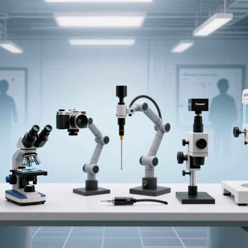
What Optical Inspection Tools Are and How They Work
Optical inspection tools use light, lenses, and sensors to reveal surface defects or measure visible features. A hand lens helps locate scratches; a digital microscope records fine edges; automated optical inspection (AOI) captures images and flags differences against programmed limits. The basic chain is simple: illuminate, focus, capture, compare. But lighting matters. A low-angle beam can make a tiny burr cast a sharp shadow, while glare may hide a shallow crack.
Systems may use bright-field, dark-field, or coaxial illumination, chosen for the material and defect. A camera converts reflected light into pixels; software checks contrast, shape, position, or dimensions. Some tools use structured light to estimate height, though reflective or transparent surfaces can confuse readings. Operators still need calibrated scales, stable fixtures, and reference samples. A beautiful image is not automatically a reliable measurement.
Industry scale helps explain the value of repeatable visual checks. The International Federation of Robotics reported 4,281,585 industrial robots operating in factories worldwide in 2023, in its World Robotics 2024 report. Optical inspection often works alongside automation, checking parts without touching them. Yet tool choice depends on the question: finding a stain differs from verifying a hole diameter. In practice, setting thresholds can be awkward. Too strict, and good parts fail. Too loose, and defects pass.
What Are the Best Optical Inspection Tools in 2026? — What Optical Inspection Tools Are and How They Work
| Optical Inspection Tool | How It Works | Typical Measurements or Findings | Best Suited For | Key Advantages | Important Limitations |
|---|---|---|---|---|---|
| Optical comparator (profile projector) | Projects a magnified silhouette of a part onto a screen. The operator compares the profile with a screen reticle or measures coordinates and angles. | External profiles, radii, angles, distances, and contour features. | Checking small machined parts, formed components, and two-dimensional outlines. | Provides a clear, enlarged view and is straightforward for profile comparisons. | Primarily measures projected two-dimensional features; results depend on setup, focus, and operator interpretation. |
| Measuring microscope | Uses magnified optics with a calibrated stage, reticle, or digital coordinate system to locate and measure visible features. | Small distances, hole spacing, edge positions, and fine surface details. | Small components and features that require magnification with dimensional measurement. | Combines detailed visual inspection with precise positioning of small features. | Field of view is limited at higher magnification; measurements generally require a stable, well-focused setup. |
| Video measuring system (vision measuring machine) | A camera captures the part, while software detects edges or other features and calculates dimensions from calibrated image coordinates. | Lengths, diameters, hole positions, angles, and two-dimensional geometric relationships. | Repeatable inspection of small or flat parts with multiple measurable features. | Automates image-based measurements and can store inspection routines for repeated jobs. | Accuracy can be affected by lighting, edge contrast, focus, calibration, and part orientation; hidden or steep features may be difficult to measure. |
| Stereo microscope | Two optical paths provide a three-dimensional perception of the sample at relatively low magnification. | Visible defects, assembly conditions, surface features, and general shape. | Hands-on inspection, sorting, rework, and examination of larger components. | Offers depth perception and a generous working distance for manipulating samples. | Usually supports visual assessment rather than calibrated, high-accuracy dimensional measurement. |
| Digital microscope | A camera and lens display a magnified image on a monitor; some systems add measurement, image capture, and focus-stacking functions. | Surface defects, feature dimensions within the calibrated image plane, and documented visual evidence. | Inspection and documentation where shared screen viewing or image records are useful. | Images are easy to capture, share, and annotate; some models provide on-screen measurement tools. | Measurement reliability depends on calibration, optics, focus, and viewing geometry; a two-dimensional image may not show true depth. |
| Confocal microscope | Rejects out-of-focus light using a spatial aperture and builds optical sections at different focal depths. | Surface topography, height differences, roughness-related characteristics, and structures with some depth variation. | Microscopic surface analysis when optical sectioning or height information is required. | Can generate depth-resolved surface data without physically touching the sample. | Results depend on reflectivity, surface shape, setup, and the instrument's measurement range; acquisition can be slower than broad-area imaging. |
| Optical interferometer | Combines light reflected from a reference path and a test surface. The resulting interference pattern is analyzed to calculate surface shape or displacement. | Surface flatness, step height, and microscopic surface form, depending on the instrument configuration. | Precision evaluation of smooth, reflective surfaces and small height variations. | Can measure very small surface-height differences without contact. | Vibration, surface reflectivity, steep slopes, and environmental conditions can affect measurement quality. |
| Automated optical inspection (AOI) system | One or more cameras capture images under controlled illumination; software compares features with programmed rules or reference data. | Presence or absence, placement, orientation, visible defects, and selected dimensional characteristics. | High-throughput inspection of repeated products, including electronic assemblies and manufactured components. | Supports fast, consistent inspection and automatic recording or rejection decisions. | Detects only features that are visible under the chosen optics and lighting; false calls and missed defects can occur if programs are poorly tuned. |
Selection tip: Choose a tool according to the feature to be inspected, required measurement uncertainty, part geometry, surface finish, inspection speed, and need for traceable records. Optical inspection results should be validated for the specific part and measurement process.